- Share 1-6 Telephone Lines Between Multiple Desktop Modems or other voice or FAX equipment
- Connect Them at the Work Group or in the Wire Closet
- Use Them Instead of Expensive Access Servers
- No LAN Overhead or Connection Required
- Minimal Signal Loss From the Central Office
- Aborts Inbound Calls to Non-Existent Devices
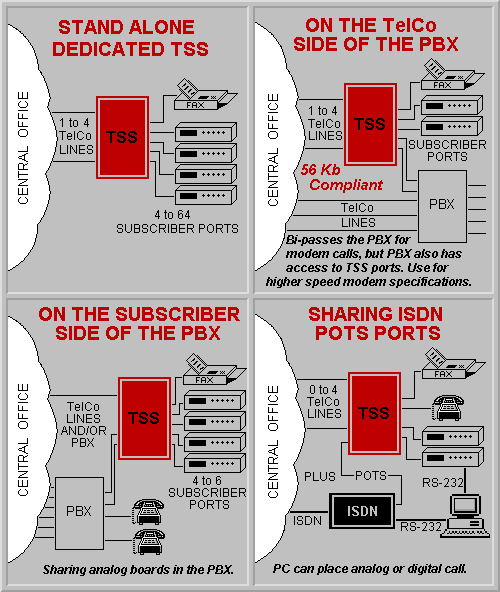
- Use With PBXs on the User Side or the TelCo side
- Share the POTS Port on ISDN Modems
|

|
The TSS family of automatic telephone line sharing switches is designed to allow
multiple desktop modems, faxes, etc. to share a lesser number of "outside"
telephone lines.
Although, the TSS switches are primarily designed for dial out modem applications,
FAXes, PBXes, voice sets, credit card scanners or other analog devices, they can
also be connected to designated station ports to receive incoming calls. The TSSs
are completely automatic and require no programming or codes to be entered.
They operate "on the fly" passing the central office signal straight
through to the modem so there is no additional delay or signal reduction. In
addition to automatically connecting "the biding" device to the line, they
also prevent other devices from interfering with an established connection.
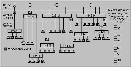
The probability of a user accessing a non-busy line increases exponentially with
the number of lines available (see Multi-Line Models).
This also allows line utilization to increase to a higher percentage before
additional lines may be considered.
Many on-line services may only be used occasionally making it difficult to justify
a dedicated dial line to each desktop. The answer is to allow multiple users to
share these lines. Other methods of sharing TelCo lines, such as RS-232 sharing
switches, LAN modem servers or adding analog cards to a PBX, if capable, are expensive
and complicated and may not address the issue of utilizing the desktop modems.
The TSS family of switches is the most practical, economical and straightforward
solution to sharing TelCo lines.
VARIOUS MODELS
To meet your specific requirements, the TSS Switches are available in several
different models.
They are differentiated by the number of telephone lines that they support as
well as the number of station ports that they provide. As an example, the 2x8
supports two telephone lines and provides eight station ports for the user
connections. All of the ports are presented through standard RJ-11 TelCo
connectors.
The other difference between models is the method by which they receive power.
The "Signal Powered" version (-S) receives its operating power
from the TelCo line and the "AC Powered" versions (-M) are powered
from a separate 9VAC wall mounted transformer. The (-P) includes a priority
interrupt.
The (-S) versions can operate as stand alone units when the users are clustered
in relatively close proximity. They will support about 150' of cable from each
of the station ports. However, the (-S) versions must be connected to a (-M)
if used in a daisy chained configuration. All of the multi-phone line units are
AC powered, (-M) versions.
The (-M) versions are normally located in the wire closet. They support long
cable runs from each station port and provide additional signal filtration.
They can support one (-S) unit from each of the station ports.
The (-M) versions also have a ring detect circuit to handle inbound calls a
little more efficiently.
CABLING
For smaller single line requirements, they can be connected at the work group
where a handy FAX line RJ-11 jack may already exist. Or, for larger multi-line
systems, they can be connected in the wire closet along with the TelCo equipment.
All of the TSS ports have standard RJ-11 TelCo connectors.
As the usage and/or the number of users increase, the number of station ports
can easily be expanded by "daisy chaining" the TSSs. Or, by
"stacking" additional EXPANSION MODULES on the EXPANDABLE BASE UNITS.
Additional telephone lines can easily be added at the beginning of the hierarchy
providing an immediate benefit to everyone on the shared network without rewiring.
SECURITY (See Challenger)
Security is always an important consideration when dealing with dial lines. The
diagram below demonstrates the possible placement of CPS's dial line security
products. They can be placed in the locked wire closet or at the work group.
Depending on their placement, they can be used to secure inbound or outbound calls
at any level.


